

-
Welcome to Tundras.com!
You are currently viewing as a guest! To get full-access, you need to register for a FREE account.
As a registered member, you’ll be able to:- Participate in all Tundra discussion topics
- Transfer over your build thread from a different forum to this one
- Communicate privately with other Tundra owners from around the world
- Post your own photos in our Members Gallery
- Access all special features of the site
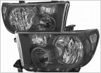 Anyone running these headlights?
 Fluids for differential and transfer case ... still confused
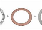 DIY front differential and transfer case fluid change.
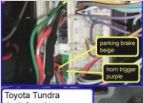 Push-button / Remote start Mod
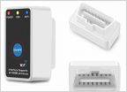 Code reader
 TRD front sway bar installation
IG1 No. 1 Relay location?
Discussion in '2nd Gen Tundras (2007-2013)' started by Tundravod, Aug 22, 2022.


