

-
Welcome to Tundras.com!
You are currently viewing as a guest! To get full-access, you need to register for a FREE account.
As a registered member, you’ll be able to:- Participate in all Tundra discussion topics
- Transfer over your build thread from a different forum to this one
- Communicate privately with other Tundra owners from around the world
- Post your own photos in our Members Gallery
- Access all special features of the site
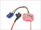 Auto stop/start disable
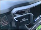 Offroam phone mount
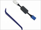 Automatic shutoff
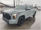 2023 Lunar Rock paint code
 Front seat have AC and heater...not there rear.
Need help wiring light bar to switch
Discussion in '3rd Gen Tundras (2022+)' started by SDHNTR, Aug 3, 2024.
Page 1 of 2
Page 1 of 2


