

-
Welcome to Tundras.com!
You are currently viewing as a guest! To get full-access, you need to register for a FREE account.
As a registered member, you’ll be able to:- Participate in all Tundra discussion topics
- Transfer over your build thread from a different forum to this one
- Communicate privately with other Tundra owners from around the world
- Post your own photos in our Members Gallery
- Access all special features of the site
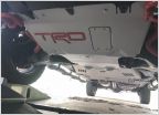 NEED HELP with TRD Skid Plate Upgrade with ReadyLift TRD pro plus-2 skid plate adaptor kit #67-5443
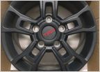 ISO TRD PRO EDITION BBS FORGED WHEELS
 Oil Change on the 2015 5.7
 Aftermarket Pioneer
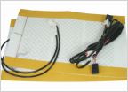 Tailgate on 2019 tundra
Heated seats
Discussion in '2.5 Gen TRD Pro (2014-2021)' started by TNVols865, Jan 3, 2025.
Page 1 of 2
Page 1 of 2
Products Discussed in


