

-
Welcome to Tundras.com!
You are currently viewing as a guest! To get full-access, you need to register for a FREE account.
As a registered member, you’ll be able to:- Participate in all Tundra discussion topics
- Transfer over your build thread from a different forum to this one
- Communicate privately with other Tundra owners from around the world
- Post your own photos in our Members Gallery
- Access all special features of the site
 Now the lift chains are a no go on the new lift
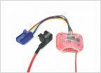 Auto stop/start disable
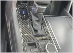 Carbon Fiber Interior
 Rim touch up paint
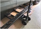 Installing Westcott sliders
3rd Gen (eBay Import) Powered Bed Step Install Instructions (Now in English!)
Discussion in '3rd Gen Tundras (2022+)' started by Leatherhead237, Aug 12, 2023.


