

-
Welcome to Tundras.com!
You are currently viewing as a guest! To get full-access, you need to register for a FREE account.
As a registered member, you’ll be able to:- Participate in all Tundra discussion topics
- Transfer over your build thread from a different forum to this one
- Communicate privately with other Tundra owners from around the world
- Post your own photos in our Members Gallery
- Access all special features of the site
 Headlights? Ideas?
 07 Tundra limited 4d 4x4 tire cupping???
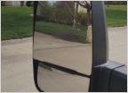 All in one mirror and blind spot mirror
 AC Performance
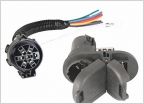 2008 trailer harness
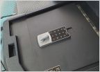 Console safe
Crankshaft sensor wiring diagram?
Discussion in '2nd Gen Tundras (2007-2013)' started by CarTop, Nov 11, 2022.


