

-
Welcome to Tundras.com!
You are currently viewing as a guest! To get full-access, you need to register for a FREE account.
As a registered member, you’ll be able to:- Participate in all Tundra discussion topics
- Transfer over your build thread from a different forum to this one
- Communicate privately with other Tundra owners from around the world
- Post your own photos in our Members Gallery
- Access all special features of the site
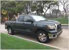 Here we go: 2007 Tundra Extra Cab build
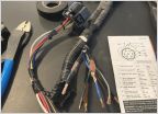 Need trailer harness part numbers
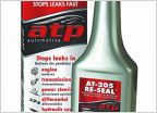 Blue smoke out of the exhaust.
 High Beam Foot Switch
 Has anyone tried the hooke bumper?
 Backup Camera
Electrical Mods, Fog install and LED Flasher
Discussion in '2nd Gen Tundras (2007-2013)' started by KeepOnTruckin, Mar 27, 2023.


